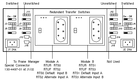
Redundant Transfer Unit
| Servers: |
Sun Fire 6800, E6900 |
| Cabinets: |
Sun Fire Cabinet |
| 300-1335 |
300-1927 |
300-2033 |
|
E6900
L
See RoHS
Note below |
E6900
L |

Sun Fire 3800-6800 Codename: Serengeti
Sun Fire E6900 Codename: Amazon 6 |
RoHS Note
- 300-1927 contains a non-RoHS-compliant hex-chrome connector.
A hex-chrome waiver allowed the use of this part in RoHS
configurations, but the waiver expired on 30 June 2007.
300-2033 is now required for RoHS configurations.
Notes
- Output Group 1, J1 and J2, is protected by a fuse.
 J1 is only to be used on the Sun Fire 6800 configuration. J1 is only to be used on the Sun Fire 6800 configuration.
 J2 is never to be used. Using RTU J2 may damage your system. J2 is never to be used. Using RTU J2 may damage your system.
- Output Group 2, J3-J10, is protected by circuit breakers CB3-CB10.
- Output Group 3, J11 and J12, is protected by a fuse.
- Maximum output of the Mate-N-Lok connector is 12A.
- The maximum combined output for all RTU power outlets is 24A.
- Only one RTS in an RTU is active. The second RTS is a backup.
- Two independent AC power sources are required for redundancy.
- The two AC power sources must be from independent utility feeds.
- Connect RTS 1 and RTS 2 to one AC power source, and
connect RTS 0 and RTS 3 to the other AC power source
(see
Redundant Transfer Switch for full description).
- An unswitched power connection (J11 or J12) will be active
only when its associated RTS is connected to a power source.
 J11 is active when RTS 0 is connected. J11 is active when RTS 0 is connected.
 J12 is active when RTS 1 is connected. J12 is active when RTS 1 is connected.
Labeling Notes
- The Redundant Transfer Unit abbreviation is RTU.
- The Redundant Transfer Switch abbreviation is RTS.
- The front and rear locations are abbreviated F and R.
- Chassis labels include the abbreviated name, location, and number.
Peripheral Power Cable Notes
- Two Meter Peripheral Power Cable 180-1945 is connected to Rear RTU J3
through J11 on assembly 540-3353-04 prior to 1 March 2002.
- Three Meter Peripheral Power Cable 180-1948 is connected to Rear RTU
J3 J5 J7 J9 and Front RTU J3 J5 J7 J9 on assembly 540-3353-05 effective
1 March 2002.
Refer to drawing 386-4456-05, eco wo_22331.
- Fantray 0 Power Cable to Rear RTU J11 was changed from 180-1945 to 180-1948
on assembly 540-3353-05 effective 1 March 2002.
References
 Sun Fire Systems Service Manual, 805-7363.
 Sun Fire 6800 System Installation Guide, 805-7375.
 Sun Fire Cabinet Installation Guide, 806-2942.
 Redundant Transfer Unit Installation Guide, 806-4717.
 Sun Fire 6800 System and Sun Fire Cabinet Rackmount Placement Matrix,
816-2062.
 Sun Fire E4900/E6900 Systems Service Manual, 817-4120.
|

