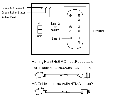
Redundant Transfer Switch
| Servers: |
Sun Fire 6800, E6900 |
| Cabinets: |
Sun Fire Cabinet |
| 300-1396 |
300-1928 |
300-2032 |
200-240VAC
47/63Hz 24A |
200-240VAC
47/63Hz 24A
E6900
L
See RoHS
Note below |
200-240VAC
47/63Hz 24A
E6900
L |

| LED |
STATUS |
DESCRIPTION |
| Left Green |
On
Off
Flashing |
AC present
AC not present or below specification
AC above specification |
| Middle Green |
On
Off
Flashing |
Relay energized
Relay de-energized and RTS is installed
Relay de-energized and RTS is not installed |
| Right Amber |
On
Off |
Fault
Normal |
Sun Fire 3800-6800 Codename: Serengeti
Sun Fire E6900 Codename: Amazon 6 |
RoHS Note
- 300-1928 contains a non-RoHS-compliant hex-chrome connector.
A hex-chrome waiver allowed the use of this part in RoHS
configurations, but the waiver expired on 30 June 2007.
300-2032 is now required for RoHS configurations.
Notes
- The Redundant Transfer Unit abbreviation is RTU.
- The Redundant Transfer Switch abbreviation is RTS.
- The front and rear locations are abbreviated F and R.
- Chassis labels include the abbreviated name, location, and number.
- Two totally independent AC power sources are needed for input power
redundancy. The power sources must be derived from independent
power company utility feeds, and Sun recommends that each be backed
up with an online UPS. The power sources are not independent if
they are only distinguished by having separate circuit breakers.
- In configurations with two independent AC power sources, there will
be four cables to connect, two on the front, and two on the rear of
the system. Connect RTS 2 (front) and RTS 1 (rear) to one power source,
and RTS 3 (front) and RTS 0 (rear) to the other power source:

- In configurations with only one AC power source, there will be two
cables to connect, one on the front (on the left), and one on the
rear of the system (on the left). These are the default RTS units,
RTS 2 and RTS 0 respectively:

- Connecting the alternate RTS units to outlets that use the same power
source as the default RTS units is not supported and will adversely
affect reliability.
References
 Sun Fire Systems Service Manual, 805-7363.
 Sun Fire 6800 System Installation Guide, 805-7375.
 Sun Fire Cabinet Installation Guide, 806-2942.
 Redundant Transfer Switch Installation Guide, 806-4716.
 Sun Fire 6800 System and Sun Fire Cabinet Rackmount Placement Matrix,
816-2062.
 Sun Fire E4900/E6900 Systems Service Manual, 817-4120.
|

