| Home | Current Systems | Former STK Products | EOL Systems | Components | General Info | Search | Feedback |
|
|
Sun System Handbook - ISO 3.4 June 2011 Internal/Partner Edition | ||
|
|||
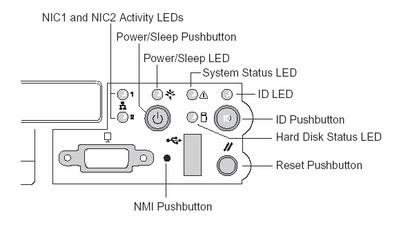
Sun[tm] Fire V60x and V65x LEDsFront Panel LEDs
Front-Panel System Status LEDCritical ConditionA critical condition or non-recoverable threshold crossing is indicated with a continuous amber status LED and is associated with the following events:
Non-Critical ConditionA non-critical condition is indicated with a blinking amber status LED and signifies that at least one of the following conditions is present:
Degraded ConditionA degraded condition is indicated with a blinking green status LED and signifies that at least one of the following conditions is present:
Refer to the Sun Fire V60x and Sun Fire V65x servers Troubleshooting Guide for information on how to isolate the server component responsible for any of the critical, non-critical, or degraded conditions listed above. Rear Panel LEDs | |||||||||||||||||||||||||||||||||||||||||||||||||||||||||||||||||||||||||||||||||||||||||||||||||||||||||||||||||||||||||||||||||||||||||||||||||||||||||||||||||||||||||||||||||||||||||||||||||||||||||||||||||||||||||||||||||||||||||||||||||||||||||||||||||||||||||||||||||||||||||||||||||||||||||||||||||||||||||||||||||||||||||||||||||||||||||||||||||||||||||||||||||||||||||||||||||||||||||||||||||||||||||||||||||||||||||||||||||||||||||||||||||||||||||||||||||||||||||||||||||||||||||||||||||||||||||||||||||||||||||||||||||||||||||||||||||||||||||||||||||||||||||||||||||||||||||||||||||||||||||||||||||||||||||||||||||||||||||||||||||||
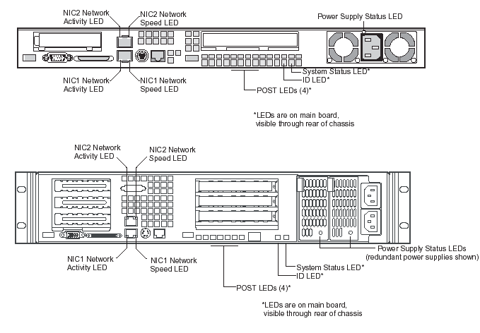
|
LED |
Color |
Function |
|---|---|---|
|
Network Connection/ Network Activity |
Green |
This LED is on the left side of each NIC connector.
|
|
Network Speed |
Amber/Green |
This LED is on the right side of the NIC connector.
|
|
POST LEDs (four) |
Multicolor (Red/Green/Amber) |
To help diagnose power-on self test (POST) failures, a set of four bi-color diagnostic LEDs is located on the back edge of the server Main Board. These LEDs are visible through holes in the rear panel. Each of the four LEDs can have one of four states: Off, Green, Red, or Amber. For detailed information on these LEDs, see POST LED Indicators. |
|
System ID |
Blue |
This LED is located on the Main Board and is visible through holes in the rear panel. It can provide a mechanism for identifying one system out of a group of identical systems. This can be particularly useful if the server is used in a rack-mount chassis in a high-density, multiple-system application. The LED is activated by depressing the front panel System ID pushbutton or if the server receives a remote System Identify command from a remote management console. If activated by the front panel pushbutton, the LED remains on until the pushbutton is depressed again. When the LED illuminates due to a remote System Identify command, the LED turns off after a timeout period. An additional blue System ID LED is located on the front panel that mirrors the operation of the rear Main Board LED. |
|
System Status/Fault |
Green/Amber |
This LED reflects the state of the System Status LED on the front panel. |
|
Power Supply |
Green/Amber |
This is a bi-color LED that can be on, off, green, amber, or blinking, or combination thereof. See Rear Panel Power Supply Status LED for more detailed information. |
|
Power Supply LED State |
Power Supply Condition |
|---|---|
|
OFF |
No AC power present to power supply |
|
BLINKING GREEN |
AC power present, but only the standby outputs are on |
|
GREEN |
Power supply DC outputs on and OK |
|
BLINKING AMBER |
PSAlert# signal asserted, power supply on |
|
AMBER |
Power supply shutdown due to over current, over temperature, over voltage, or undervoltage |
|
AMBER or OFF |
Power supply failed and AC fuse open or other critical failure |
|
Note - If redundant power supplies are used in
the Sun Fire V65x server, the power supply LEDs have the following meaning:
|
To help diagnose POST failures, a set of four bi-color diagnostic LEDs is located on the back edge of the server Main Board. Each of the four LEDs can have one of four states: Off, Green, Red, or Amber.
The LED diagnostics feature consists of a hardware decoder and four dual color LEDs. During boot block POST and post boot block POST, the LEDs display all normal Port80 codes representing the progress of the BIOS POST. Each POST code is represented by a combination of colors from the four LEDs. The LEDs are in pairs of green and red. The POST codes are broken into two nibbles, an upper and a lower nibble. Each bit in the upper nibble is represented by a red LED and each bit in the lower nibble is represented by a green LED. If both bits are set in the upper and lower nibble then both red and green LEDs are lit, resulting in an amber color. Likewise, if both bits are clear then the red and green LEDs are off.
During the POST process, each light sequence represents a
specific Port-80 POST code. If a system should hang during POST, the diagnostic
LEDs present the last test executed before the hang. When you read the LEDs,
observe them from the back of the system. The most significant bit (MSB) is
the leftmost LED, and the least significant bit (LSB) is the rightmost LED.
|
Note - When comparing a diagnostic LED color string from the server Main Board to those listed in the diagnostic LED decoder in the following tables, the LEDs on the Main Board should be referenced when viewed by looking into the system from the back. Reading the LEDs from left to right, the most-significant bit is located on the left. |
|
POST Code |
Diagnostic LED Decoder |
Description |
|||
|---|---|---|---|---|---|
|
|
MSB |
|
|
LSB |
|
|
10h |
Off |
Off |
Off |
R |
The NMI is disabled. Start power-on delay. Initialization code checksum verified. |
|
11h |
Off |
Off |
Off |
A |
Initialize the DMA controller, perform the keyboard controller BAT test, start memory refresh, and enter 4 GB flat mode. |
|
12h |
Off |
Off |
G |
R |
Get start of initialization code and check BIOS header. |
|
13h |
Off |
Off |
G |
A |
Memory sizing. |
|
14h |
Off |
G |
Off |
R |
Test base 512K of memory. Return to real mode. Execute any OEM patches and set up the stack. |
|
15h |
Off |
G |
Off |
A |
Pass control to the uncompressed code in shadow RAM. The initialization code is copied to segment 0 and control will be transferred to segment 0. |
|
16h |
Off |
G |
G |
R |
Control is in segment 0. Verify the system BIOS checksum. If the system BIOS checksum is bad, go to checkpoint code E0h; otherwise, going to checkpoint code D7h. |
|
17h |
Off |
G |
G |
A |
Pass control to the interface module. |
|
18h |
G |
Off |
Off |
R |
Decompression of the main system BIOS failed. |
|
19h |
G |
Off |
Off |
A |
Build the BIOS stack. Disable USB controller. Disable cache. |
|
1Ah |
G |
Off |
G |
R |
Uncompress the POST code module. Pass control to the POST code module. |
|
1Bh |
A |
R |
Off |
R |
Decompress the main system BIOS runtime code. |
|
1Ch |
A |
R |
Off |
A |
Pass control to the main system BIOS in shadow RAM. |
|
E0h |
R |
R |
R |
Off |
Start of recovery BIOS. Initialize interrupt vectors, system timer, DMA controller, and interrupt controller. |
|
E8h |
A |
R |
R |
Off |
Initialize extra module if present. |
|
E9h |
A |
R |
R |
G |
Initialize floppy controller. |
|
EAh |
A |
R |
A |
Off |
Try to boot floppy diskette. |
|
EBh |
A |
R |
A |
G |
If floppy boot fails, initialize ATAPI hardware. |
|
ECh |
A |
A |
R |
Off |
Try booting from ATAPI CD-ROM drive. |
|
EEh |
A |
A |
A |
Off |
Jump to boot sector. |
|
EFh |
A |
A |
A |
G |
Disable ATAPI hardware. |
POST Progress LED Code Table (Port 80h Codes)
|
POST Code |
Diagnostic LED Decoder |
Description |
|||
|---|---|---|---|---|---|
|
|
MSB |
|
|
LSB |
|
|
20h |
Off |
Off |
R |
Off |
Uncompress various BIOS modules. |
|
22h |
Off |
Off |
A |
Off |
Verify password checksum. |
|
24h |
Off |
G |
R |
Off |
Verify CMOS checksum. |
|
26h |
Off |
G |
A |
Off |
Read microcode updates from BIOS ROM. |
|
28h |
G |
Off |
R |
Off |
Initializing the processors. Set up processor registers. Select least featured processor as the BSP. |
|
2Ah |
G |
Off |
A |
Off |
Go to Big Real mode. |
|
2Ch |
G |
G |
R |
Off |
Decompress INT13 module. |
|
2Eh |
G |
G |
A |
Off |
Keyboard controller test: The keyboard controller input buffer is free. Next, the BAT command will be issued to the keyboard controller. |
|
30h |
Off |
Off |
R |
R |
Swap keyboard and mouse ports, if needed. |
|
32h |
Off |
Off |
A |
R |
Write command byte 8042: The initialization after the keyboard controller BAT command test is done. The keyboard command byte will be written next. |
|
34h |
Off |
G |
R |
R |
Keyboard Init: The keyboard controller command byte is written. Next, the pin 23 and 24 blocking and unblocking commands will be issued. |
|
36h |
Off |
G |
A |
R |
Disable and initialize the 8259 programmable interrupt controller. |
|
38h |
G |
Off |
R |
R |
Detect configuration mode, such as CMOS clear. |
|
3Ah |
G |
Off |
A |
R |
Chipset initialization before CMOS initialization. |
|
3Ch |
G |
G |
R |
R |
Init system timer: The 8254 timer test is over. Starting the legacy memory refresh test next. |
|
3Eh |
G |
G |
A |
R |
Check refresh toggle: The memory refresh line is toggling. Checking the 15 second on/off time next. |
|
40h |
Off |
R |
Off |
Off |
Calculate CPU speed. |
|
42h |
Off |
R |
G |
Off |
Init interrupt vectors: Interrupt vector initialization is done. |
|
44h |
Off |
A |
Off |
Off |
Enable USB controller in chipset. |
|
46h |
Off |
A |
G |
Off |
Initialize SMM handler. Initialize USB emulation. |
|
48h |
G |
R |
Off |
Off |
Validate NVRAM areas. Restore from backup if corrupted. |
|
4Ah |
G |
R |
G |
Off |
Load defaults in CMOS RAM if bad checksum or CMOS clear jumper is detected. |
|
4Ch |
G |
A |
Off |
Off |
Validate date and time in RTC. |
|
4Eh |
G |
A |
G |
Off |
Determine number of microcode patches present. |
|
50h |
Off |
R |
Off |
R |
Load microcode to all CPUs. |
|
52h |
Off |
R |
G |
R |
Scan SMBIOS GPNV areas. |
|
54h |
Off |
A |
Off |
R |
Early extended memory tests. |
|
56h |
Off |
A |
G |
R |
Disable DMA. |
|
58h |
G |
R |
Off |
R |
Disable video controller. |
|
5Ah |
G |
R |
G |
R |
8254 timer test on channel 2. |
|
5Ch |
G |
A |
Off |
R |
Enable 8042. Enable timer and keyboard IRQs. Set video mode: Initialization before setting the video mode is complete. Configuring the monochrome mode and color mode settings next. |
|
5Eh |
G |
A |
G |
R |
Initialize PCI devices and motherboard devices. Pass control to video BIOS. Start serial console redirection. |
|
60h |
Off |
R |
R |
Off |
Initialize memory test parameters. |
|
62h |
Off |
R |
A |
Off |
Initialize AMI display manager module. Initialize support code for headless system if no video controller is detected. |
|
64h |
Off |
A |
R |
Off |
Start USB controllers in chipset. |
|
66h |
Off |
A |
A |
Off |
Set up video parameters in BIOS data area. |
|
68h |
G |
R |
R |
Off |
Activate ADM: The display mode is set. Displaying the power-on message next. |
|
6Ah |
G |
R |
A |
Off |
Initialize language module. Display splash logo. |
|
6Ch |
G |
A |
R |
Off |
Display sign on message, BIOS ID, and processor information. |
|
6Eh |
G |
A |
A |
Off |
Detect USB devices. |
|
70h |
Off |
R |
R |
R |
Reset IDE Controllers. |
|
72h |
Off |
R |
A |
R |
Displaying bus initialization error messages. |
|
74h |
Off |
A |
R |
R |
Display setup message: The new cursor position has been read and saved. Displaying the hit setup message next. |
|
76h |
Off |
A |
A |
R |
Ensure timer keyboard interrupts are on. |
|
78h |
G |
R |
R |
R |
Extended background memory test start. |
|
7Ah |
G |
R |
A |
R |
Disable parity and NMI reporting. |
|
7Ch |
G |
A |
R |
R |
Test 8237 DMA controller: The DMA page register test passed. Performing the DMA controller 1 base register test next. |
|
7Eh |
G |
A |
A |
R |
Initialize 8237 DMA controller: The DMA controller 2 base register test passed. Programming DMA controllers 1 and 2 next. |
|
80h |
R |
Off |
Off |
Off |
Enable mouse and keyboard: The keyboard test has started. Clearing the output buffer and checking for stuck keys. Issuing the keyboard reset command next |
|
82h |
R |
Off |
G |
Off |
Keyboard interface test: A keyboard reset error or stuck key was found. Issuing the keyboard controller interface test command next. |
|
84h |
R |
G |
Off |
Off |
Check stuck key enable keyboard: The keyboard controller interface test is complete. Writing the command byte and initializing the circular buffer next. |
|
86h |
R |
G |
G |
Off |
Disable parity NMI: The command byte was written and global data initialization has completed. Checking for a locked key next. |
|
88h |
A |
Off |
Off |
Off |
Display USB devices. |
|
8Ah |
A |
Off |
G |
Off |
Verify RAM size: Checking for a memory size mismatch with CMOS RAM data next. |
|
8Ch |
A |
G |
Off |
Off |
Lock out PS/2 keyboard/mouse if unattended start is enabled. |
|
8Eh |
A |
G |
G |
Off |
Initialize boot devices: The adapter ROM had control and has now returned control to the BIOS POST. Performing any required processing after the option ROM returned control. |
|
90h |
R |
Off |
Off |
R |
Display IDE mass storage devices. |
|
92h |
R |
Off |
G |
R |
Display USB mass storage devices. |
|
94h |
R |
G |
Off |
R |
Report the first set of POST errors To Error Manager. |
|
96h |
R |
G |
G |
R |
Boot password check: The password was checked. Performing any required programming before Setup next. |
|
98h |
A |
Off |
Off |
R |
Float processor initialize: Performing any required initialization before the coprocessor test next. |
|
9Ah |
A |
Off |
G |
R |
Enable Interrupts 0, 1, 2: Checking the extended keyboard, keyboard ID, and NUM Lock key next. Issuing the keyboard ID command next. |
|
9Ch |
A |
G |
Off |
R |
Initialize FDD devices. Report second set of POST errors to error messager. |
|
9Eh |
A |
G |
G |
R |
Extended background memory test end. |
|
A0h |
R |
Off |
R |
Off |
Prepare and run setup: Error manager displays and logs POST errors. Waits for user input for certain errors. Execute setup. |
|
A2h |
R |
Off |
A |
Off |
Set base expansion memory size. |
|
A4h |
R |
G |
R |
Off |
Program chipset setup options, build ACPI Tables, and build INT15h E820h table |
|
A6h |
R |
G |
A |
Off |
Set display mode. |
|
A8h |
A |
Off |
R |
Off |
Build SMBIOS table and MP tables. |
|
AAh |
A |
Off |
A |
Off |
Clear video screen. |
|
ACh |
A |
G |
R |
Off |
Prepare USB controllers for operating system. |
|
AEh |
A |
G |
A |
Off |
One beep to indicate end of POST. No beep if silent boot is enabled. |
|
000h |
Off |
Off |
Off |
Off |
POST completed. Passing control to INT 19h boot loader next. |
|
Copyright © 2011 Sun Microsystems, Inc. All rights reserved. Feedback | |||