Sun Blade 8000 and Sun Blade 8000_P Modular System LEDs
Sun Blade X8400, X8420, X8440 and X8450 Server Module LEDs
For latest information, reference the  Sun Blade 8000 Series Online Information System.
Indicator LEDs are provided throughout the chassis to help you identify the operational states of various components. Locator and Power buttons are also provided on the
chassis that enable you to initiate a specific action. Indicators may exhibit one of five states: Off, Steady On, Slow Blink (on/off cycle at 1 Hz), Fast Blink (on/off cycle at 4
Hz), and Standby Blink (0.1 second on, 2.9 seconds off). Note that not all indicators use all states.
Indicators and buttons are located on these components:
-
Front and Rear Indicator Modules (FIM/RIM; chassis summary indicators on the front and rear of the chassis)
-
Power supply modules
-
Server Modules (blades)
-
PCI Express ExpressModules (EMs; Sun Blade 8000 Chassis only)
-
Network Express Modules (NEMs)
-
Chassis Monitoring Modules (CMMs)
-
Front fan modules (Sun Blade 8000 Chassis only)
-
Rear fan modules
The buttons and indicators for each component are discussed in more detail in related topics.
Button and Indicator Features
|
Button or Indicator
|
Color
|
Description
|
|
Locator indicator (chassis and blade)
|
White
|
This LED provides these indications:
You can illuminate the Locator indicator either by executing a software command on the CMM, or by momentarily pressing the associated Locator
button.
|
|
Locator button (chassis and blade)
|
|
This button provides these functions:
-
Quick press – Lights the Locator indicator.
-
Four second or more press of the Front or Rear Indicator Module (FIM/RIM) Locator button – CMM enacts a chassis-wide Lamp Test, which causes the
indicators on all replaceable components (FRUs and CRUs), front and rear, to light as long as the Locator button is pressed. Once the Locator button is released, all component
indicators return to their previous state.
|
|
Service Action Required indicator (chassis, blade, FRU/CRU)
|
Amber
|
This LED provides these indications:
-
Steady On – Indicates that the FRU or CRU, or a FRU or CRU that a module contains, is broken and needs to be replaced. The LED remains Steady On as long as
any Service Action Required indicator on any FRU or CRU in the chassis is lit.On the FIM or RIM, this LED provides a summary of all other Service Action Required FRU and CRU
indicators in the chassis.
-
Off – Service is not required.
|
|
OK indicator (chassis, blade, FRU/CRU)
|
Green
|
This LED provides these indications:
-
Slow Blink – Indicates that the unit is changing state (for example, booting).
-
Standby Blink – Indicates that the unit is being managed. The unit is not operational, but it is ready to be activated. On the FIM or RIM, this LED
indicates that the CMM has begun initialization. When the CMM has completed its initialization and has begun to actively manage the chassis, the OK indicator transitions to the
Standby Blink state. At this state, only the chassis summary indicators and CMM indicators are active.
-
Steady On – Indicates that the unit is operating normally.
-
Off – Remains off before the chassis has powered on and before the chassis has reached the Standby Blink state.
|
|
Ready-to-Remove indicator (blade, FRU/CRU)
|
Blue
|
This LED provides these indications:
|
|
Power button (chassis)
|
|
Located on the FIM and RIM, this button powers on the chassis that is in the standby state, as indicated by the OK indicator being in the Standby Blink state.
The chassis powers on by default when AC power is applied. The only time you will need to press the Power button is if the Administrator has specifically
disabled the automatic power-on feature, or if the chassis has been powered off. Therefore, it is unlikely that you will find the OK LED in the Standby Blink state.
The chassis cannot be turned off by pressing the Power button. Only an authorized Administrator, logged in to the active CMM, can turn off the chassis by
issuing a CMM software command.
|
|
Power button (blade)
|
|
Located on the front of the blade, this button provides these functions:
-
In a powered-on blade, when pressed and immediately released, the button invokes a graceful (OS aware) shutdown of the blade. If you press and immediately
release the button again, the OS will be restarted.
-
In a powered-on blade, when pressed and held for four seconds, the button invokes a forced shutdown of the blade with no OS notification. If you press and
immediately release the button again, the OS will be restarted.
-
In a powered-off blade, when pressed and immediately released, the blade is brought online and the OS is started.
|
|
Attention button (NEM) (EM; Sun Blade 8000 Chassis only)
|
|
Located on the Network Express Module and ExpressModule (Sun Blade 8000 Chassis only), this button enables you to activate (if inserting) or prepare to remove
(if removing) a NEM or EM during a hot-plug operation.
|
|
DC-OK (power supply module)
|
Green
|
Located on the power supply module, this LED provides these indications:
-
Steady On – Lights when the power supply is delivering regulated 48-volt power to the midplane.
-
Off – Indicates that DC power is off (for example, this LED is off when the chassis power is off).
|
|
AC-OK (power supply module)
|
Green
|
Located on the power supply module, this LED provides these indications:
-
Steady On – Lights when the power supply is receiving the proper 220-volts AC line voltage.
-
Off – Indicates that there is no power to the power supply module (for example, this LED is off when a power cord is not plugged in).
|
|
Active (CMM)
|
Green
|
Located on the CMM, this LED provides these indications:
|
|
Ethernet Link (CMM)
|
Green
|
Located on the CMM, this LED provides these indications:
|
|
Ethernet Activity (CMM)
|
Amber
|
Blink – Indicates that there is Ethernet activity.
|
The Sun Blade 8000 Modular System provides identical indicator and button functionality on the front and rear of the chassis. The Front Indicator Module (FIM) is located
at the upper left corner of the front panel, just above and to the left of the six power supply modules. The Rear Indicator Module (RIM) is located at the rear of the chassis,
among the chassis power inlets, between AC2 and AC3 inlets. The FIM and RIM indicator LEDs provide a summary status of the chassis operating state.
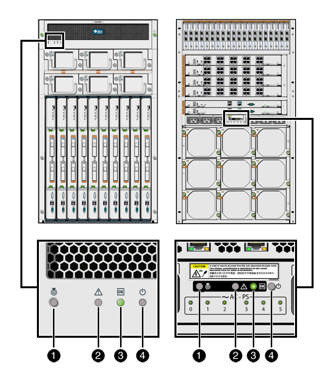
Illustration Key
|
Item
|
Button or Indicator
|
Color
|
Description
|
|
1
|
Locator indicator
|
White
|
This LED provides these indications:
You can illuminate the Locator indicator either by executing a software command on the Chassis Monitoring Module (CMM), or by momentarily pressing the
associated Locator button.
|
|
1
|
Locator button
|
|
This button provides these functions:
-
Quick press – Lights the Locator indicator.
-
Four second or more press – CMM enacts a chassis-wide Lamp Test, which causes the indicators on all replaceable components (FRUs and CRUs), front and rear,
to light as long as the Locator button is pressed. Once the Locator button is released, all FRU and CRU indicators return to their previous state.
|
|
2
|
Service Action Required indicator
|
Amber
|
This LED provides these indications:
-
Steady On – Indicates that a FRU or CRU within the chassis requires service, or that an external condition needs fixing (such as external ambient temperature
or degradation of power). This LED provides a summary of all other Service Action Required FRU and CRU indicators in the chassis. It remains Steady On as long as any Service
Action Required indicator on any FRU or CRU in the chassis is lit.
-
Off – Normal operating state.
|
|
3
|
OK indicator
|
Green
|
This LED provides these indications:
-
Standby Blink – Indicates that the CMM has begun initialization. When the CMM has completed its initialization and has begun to actively manage the chassis,
the OK indicator transitions to the Standby Blink state. At this state, only the FIM and RIM indicators and CMM indicators are active.
-
Steady On – When the chassis has been turned on fully by either pressing the Power button or executing a CMM command, the OK indicator goes to the Steady On
state.
-
Off – Remains off before the chassis has powered on and before the chassis has reached the Standby Blink state.
|
|
4
|
Power button
|
|
Powers on the chassis that is in the Standby state, as indicated by the OK indicator being in the Standby Blink state. The chassis cannot be turned off by
pressing the Power button. Only an authorized Administrator, logged in to the active CMM, can turn off the chassis by issuing a CMM software command.
|
The Sun Blade 8000 P Modular System provides identical indicator and button functionality on the front and rear of the chassis. The Front Indicator Module (FIM) is located
at the upper left corner of the front panel, just above and to the left of the four power supply modules. The Rear Indicator Module (RIM) is located at the rear of the chassis,
among the chassis power inlets, between AC1 and AC2 inlets. The FIM and RIM indicator LEDs provide a summary status of the chassis operating state.
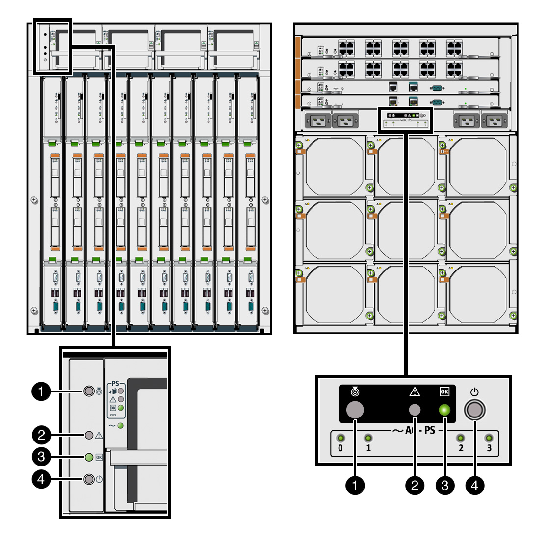
Illustration Key
|
Item
|
Button or Indicator
|
Color
|
Description
|
|
1
|
Locator indicator
|
White
|
This LED provides these indications:
You can illuminate the Locator indicator either by executing a software command on the Chassis Monitoring Module (CMM), or by momentarily pressing the
associated Locator button.
|
|
1
|
Locator button
|
|
This button provides these functions:
-
Quick press – Lights the Locator indicator.
-
Four second or more press – CMM enacts a chassis-wide Lamp Test, which causes the indicators on all replaceable components (FRUs and CRUs), front and rear,
to light as long as the Locator button is pressed. Once the Locator button is released, all FRU and CRU indicators return to their previous state.
|
|
2
|
Service Action Required indicator
|
Amber
|
This LED provides these indications:
-
Steady On – Indicates that a FRU or CRU within the chassis requires service, or that an external condition needs fixing (such as external ambient temperature
or degradation of power). This LED provides a summary of all other Service Action Required FRU and CRU indicators in the chassis. It remains Steady On as long as any Service
Action Required indicator on any FRU or CRU in the chassis is lit.
-
Off – Normal operating state.
|
|
3
|
OK indicator
|
Green
|
This LED provides these indications:
-
Standby Blink – Indicates that the CMM has begun initialization. When the CMM has completed its initialization and has begun to actively manage the chassis,
the OK indicator transitions to the Standby Blink state. At this state, only the FIM and RIM indicators and CMM indicators are active.
-
Steady On – When the chassis has been turned on fully by either pressing the Power button or executing a CMM command, the OK indicator goes to the Steady On
state.
-
Off – Remains off before the chassis has powered on and before the chassis has reached the Standby Blink state.
|
|
4
|
Power button
|
|
Powers on the chassis that is in the Standby state, as indicated by the OK indicator being in the Standby Blink state. The chassis cannot be turned off by
pressing the Power button. Only an authorized Administrator, logged in to the active CMM, can turn off the chassis by issuing a CMM software command.
|
Each power supply module has a set of four status indicator LEDs located on the module's front panel. The following illustration shows the location of these LEDs on power
supplies in the Sun Blade 8000 Chassis. The LEDs are located in a similar position on the power supplies installed in a Sun Blade 8000 P Chassis.
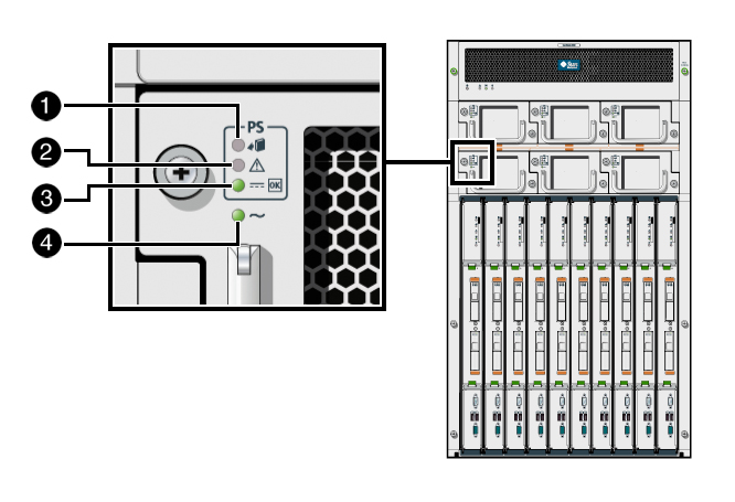
Illustration Key
|
Item
|
Indicator Name
|
Color
|
Description
|
|
1
|
Ready-to-Remove
|
Blue
|
This LED provides these indications:
|
|
2
|
Service Action Required
|
Amber
|
This LED provides these indications:
-
Steady On – Lights when the power supply detects a fault, such as overcurrent, overvoltage, or overheating. After a fault indication, you can reset the power
supply from the CMM.
-
Off – The power supply has no fault condition.
|
|
3
|
DC-OK
|
Green
|
This LED provides these indications:
-
Steady On – Lights when the power supply is delivering regulated 48-volt power to the midplane.
-
Off – Indicates that DC power is off (for example, this LED is off when the chassis power is off).
|
|
4
|
AC-OK
|
Green
|
This LED provides these indications:
-
Steady On – Lights when the power supply is receiving the proper 220-volts AC line voltage.
-
Off – Indicates that there is no power to the power supply module (for example, this LED is off when a power cord is not plugged in).
|
Each Chassis Monitoring Module (CMM) has LED indicators and recessed push buttons on the front panel, as shown in the following illustration.
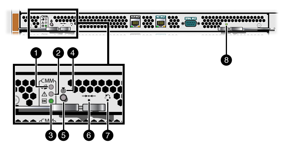
Illustration Key
|
Item
|
Indicator Name
|
Color
|
Description
|
|
1
|
Ready-to-Remove
|
Blue
|
This LED provides these indications:
|
|
2
|
Service Action Required
|
Amber
|
This LED provides these indications:
-
Steady On – Lights when there is a CMM fault, such as a power fault, memory fault, or management network link failure. In a CMM redundant configuration, if
the fault occurs in the active CMM, the standby CMM becomes active and lights the LED.
-
Off – The CMM has no fault condition.
|
|
3
|
OK
|
Green
|
This LED provides these indications:
-
Steady On – Lights steadily when AC power is applied to the chassis.
-
Slow Blink – Blinks slowly during bootup.
-
Off – Chassis has no power.
|
|
4
|
Locator button
|
|
When momentarily pressed, lights the Locator indicator.
|
|
5
|
Locator LED
|
White
|
This LED provides these indications:
|
|
6
|
Reset button
|
|
Performs a hardware reset of the CMM. Use a small stylus to activate this recessed button.
|
|
7
|
Reset password button
|
|
Resets the root password of the CMM to the factory default of changeme. Use a small stylus to activate this recessed button.
|
|
8
|
Active (Master) LED
|
Green
|
This LED provides these indications:
|
|
|
Ethernet port LEDs
|
Green (on the left)
Amber (on the right)
|
These LEDs provide these indications:
|
The Network Express Modules (NEMs) and PCI Express ExpressModules (EMs; Sun Blade 8000 Chassis only) provide a standard set of status indicators, buttons, and Ethernet
ports on their front panels.
This topic includes the following sections:
-
NEM Indicators, Buttons, and Ports
-
EM Indicators, Buttons, and Ports
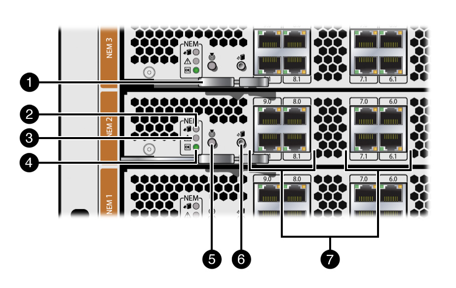
Illustration Key
|
Item
|
Indicator, Button, Port, or Component Name
|
Color
|
Description
|
|
1
|
NEM ejector lever
|
|
Open this ejector lever to replace a NEM.
|
|
2
|
Ready-to-Remove indicator
|
Blue
|
This LED provides these indications:
|
|
3
|
Service Action Required indicator
|
Amber
|
This LED provides these indications:
|
|
4
|
OK indicator
|
Green
|
This LED provides these indications:
-
Steady On – Lights steadily when the NEM is operating normally or when the NEM is not ready for removal.
-
Slow Blink – Blinks slowly when the NEM is transitioning from one state to the next.
-
Standby Blink – Blinks more slowly when the NEM is operational, but is not yet activated.
-
Off – The NEM has no power or one of the other LEDs is lit.
|
|
5
|
Locator button and indicator
|
White
|
This button provides this function:
This LED provides these indications:
-
Fast Blink – Identifies a specific NEM in the chassis. Lights when the LED is initiated from the web interface remotely or from a press of the Locator
button locally.
-
Off – The NEM locator function has not been selected.
|
|
6
|
Attention button
|
|
This button provides this function:
|
|
7
|
Network port
|
Green or amber
|
These LEDs provide these indications:
-
Green LED on left – Blinks to show both Ethernet link and activity.
-
LED on right – Shows 10-Mbit link speed when OFF.
-
Green LED on right – Shows 100-Mbit speed when ON.
-
Amber LED on right – Shows 1000-Mbit link speed when ON.
|
Illustration Key
|
Item
|
Indicator, Button, Port, or Component Name
|
Color
|
Description
|
|
1
|
EM ejector lever
|
|
Open this ejector lever to replace an EM.
|
|
2
|
EM network port
|
|
Port types will vary depending on the type of EM installed.
|
|
3
|
Power indicator
|
Green
|
This LED provides these indications:
-
Steady On – Lights steadily when the EM is operating normally or when the EM is not safe for removal.
-
Slow Blink – Blinks slowly when the EM is transitioning from one state to the next.
-
Standby Blink – Blinks more slowly when the EM is operational, but is not yet activated.
-
Off – The EM has no power and it is safe to remove the module.
|
|
4
|
Attention button
|
|
This button provides this function:
|
|
5
|
Attention indicator
|
Amber
|
This LED provides these indications:
|
On the front of the Sun Blade 8000 Chassis are three fan modules that cool the PCI Express ExpressModules. On the rear of the Sun Blade 8000 Chassis and 8000 P Chassis are
nine fan modules that cool the blades. Integrated within the power supply modules are fans that cool these supplies.
Front fan modules are supported on the Sun Blade 8000 Chassis only, as shown in the following illustration.
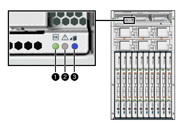
Illustration Key
|
Item
|
Indicator Name
|
Color
|
Description
|
|
1
|
OK
|
Green
|
Lights when the fan is operating normally.
|
|
2
|
Service Action Required
|
Amber
|
Lights when the Chassis Monitoring Module has diagnosed the fan as faulted and the fan needs to be replaced.
|
|
3
|
Ready-to-Remove
|
Blue
|
Lights when it is safe to remove the fan for service (the fan will still be spinning).
|
The following illustration shows the location of the rear fan modules in the Sun Blade 8000 Chassis. The rear fan modules are located in a similar position in the Sun
Blade 8000 P Chassis.
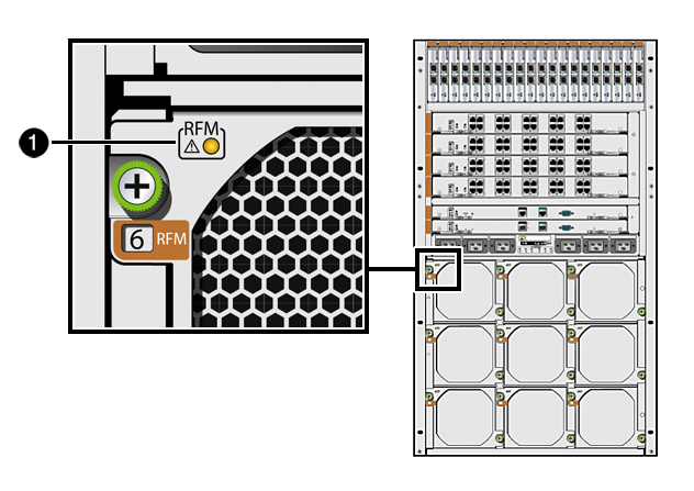
Illustration Key
|
Item
|
Indicator Name
|
Color
|
Description
|
|
1
|
OK/Service Action Required
|
Green/Amber
|
This single LED provides these indications:
-
Lights green when the fan module is operating normally.
-
Lights amber when the fan module is running too slowly or not at all and needs to be replaced.
-
Turns off when the fan module is ready for removal.
|
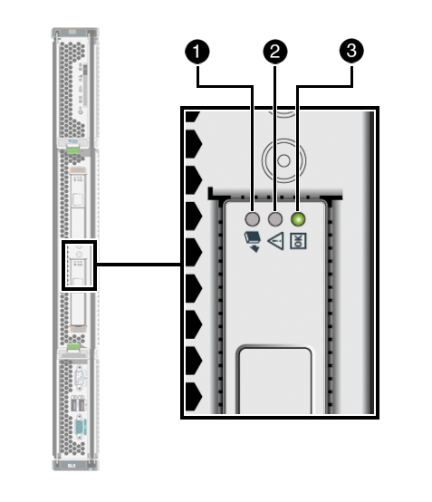
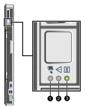
Each hard disk drive (HDD) has three LED indicators. The following illustrations highlight the location of the LEDs.
|
HDD Indicators on X8400, X8420, X8440 Server Modules
|
HDD Indicators on X8450 Server Module
|
Illustration Key
|
Item
|
Indicator
|
Color
|
Description
|
|
1
|
Ready-to-Remove
|
Blue
|
Lights when the ILOM web interface or command-line interface has been used to prepare the disk drive for removal. (This feature is currently not
available.)
|
|
2
|
Service Action Required
|
Amber
|
Lights when the disk controller detects the failure of the drive.
|
|
3
|
OK/Activity
|
Green
|
This LED provides these indications:
-
Steady On – Indicates the disk drive is installed, but is idle.
-
Fast Blink – Indicates the disk drive is actively being accessed by the disk controller.
|
The following illustration highlights the locations of the indicator LEDs and buttons on the X8400, X8420, and X8440 Server Modules.
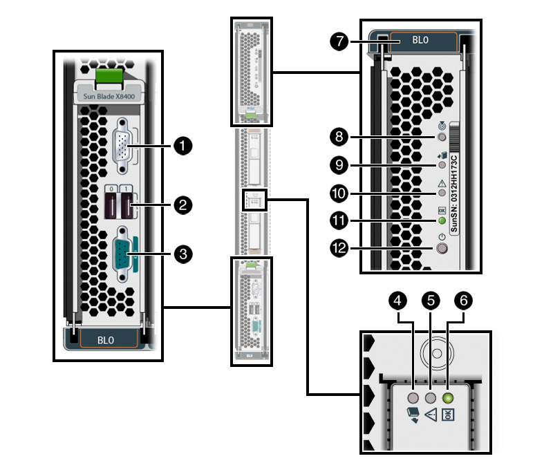
Illustration Key
|
Item
|
Description
|
|
1
|
VGA video port
|
|
2
|
USB ports (2)
|
|
3
|
Serial port
|
|
4
|
Disk drive – Ready-to-Remove LED
|
|
5
|
Disk drive – Service Action Required LED
|
|
6
|
Disk drive – OK/Activity LED
|
|
7
|
Blade slot number
|
|
8
|
Blade Locator button
|
|
9
|
Blade Ready-to-Remove LED
|
|
10
|
Blade Service Action Required LED
|
|
11
|
Blade OK LED
|
|
12
|
Blade Power button
|
The following illustration highlights the locations of the indicator LEDs and buttons on the X8450 Server Module.
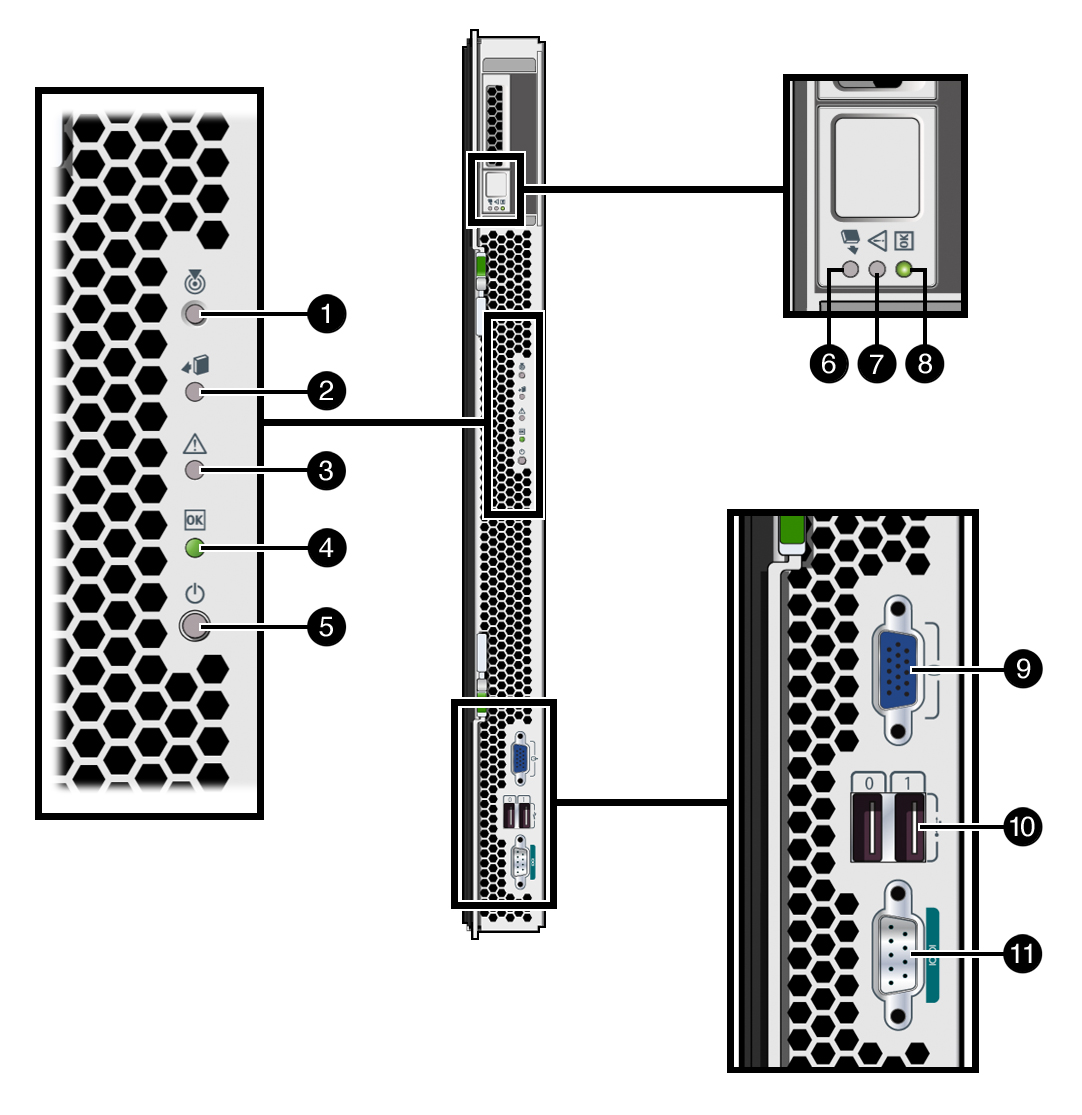
Illustration Key
|
Item
|
Description
|
|
1
|
Server module Locator button and LED
|
|
2
|
Server module Ready-to-Remove LED
|
|
3
|
Server module Service Action Required LED
|
|
4
|
Server module OK LED
|
|
5
|
Server module Power button
|
|
6
|
Disk drive Ready-to-Remove LED
|
|
7
|
Disk drive Service Action Required LED
|
|
8
|
Disk drive OK / Activity LED
|
|
9
|
VGA port
|
|
10
|
USB ports (2)
|
|
11
|
Serial port
|
|
|
|
|