| Home | Current Systems | Former STK Products | EOL Systems | Components | General Info | Search | Feedback |
|
|
Sun System Handbook - ISO 3.4 June 2011 Internal/Partner Edition | ||
|
|||
Sun StorageTek[tm] 2500 Series Array LEDs
Front Panel LEDs
Front Panel LEDs - Disk Drives | |||||||||||||||||||||||||||||||||||||||||||||||||||||||||||||||||||||||||||||||||||||||||||||||||||||||||||||||||||||||||||||||||||||||||||||||||||||||||||||||||||||||||||||||||||||||||||||||||||||||||||||||||||||||||||
| Disk Drive LED Description | ||
|---|---|---|
|
LED Name
|
Color
|
General Behavior
|
|
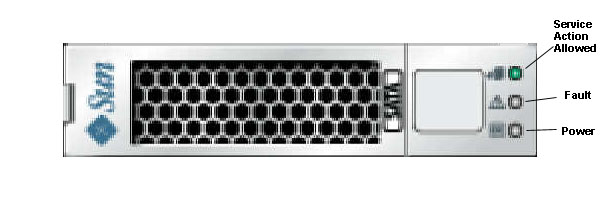
Service Action Allowed
|
Blue | Off - The disk drive cannot be removed from the tray. On - The disk drive can be removed from the tray. |
|
Fault
|
Amber | Off - Normal condition. On - The disk drive has a problem. |
|
Power
|
Green | Off - The power is turned off. On - The power is on and the disk drive is operating normally. On and blinking - Disk drive I/O activity is taking place. |
| Disk Drive LED States | ||
|---|---|---|
| Power LED (Green) | Fault LED (Amber) | Disk Drive State |
|
Off
|
Off
|
Power is no applied |
|
On, solid
|
Off
|
Normal operation, power is turned on, no disk drive I/O activity is occurring. |
|
On, blinking
|
Off
|
Normal operation, disk drive I/O activity is occurring. |
|
On, solid
|
On, solid
|
Service action required, a fault condition exists, and the drive is offline. |
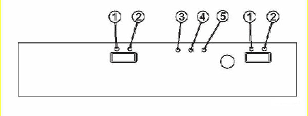
| Location | LED Name | Color | On | Off |
|---|---|---|---|---|
|
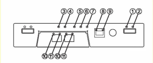
1
|
Link Fault | Amber | At least one link has an error | Normal condition. |
|
2
|
Drive Link | Green | At least one link is active | At least one link has an error. |
|
3
|
Battery Fault | Amber | Indicates a fault within the battery backup unit. | Normal condition. |
|
4
|
Cache Active | Green | Caching is enabled. When blinking, the cache has data. |
Indicates a problem if caching is enabled. |
|
5
|
Service Action Allowed | Blue | The controller can be removed from the controller tray. | The controller cannot be removed from the controller tray. |
|
6
|
Service Action Required (Fault) | Amber | Indicates fault within the controller. | Normal condition. |
|
7
|
Power | Green | Power is present. | No power is applied to the controller tray. |
|
8
|
Ethernet Link | Green | The connection is active. | The connection is not active. |
|
9
|
Ethernet 100BASE-TX | Green | 100BASE-TX connection is active. | 100BASE-TX connection is not active. |
|
10 & 11
|
Host Link | Green | Both LEDs on indicate 4-Gb/sec. data rate from the management
software host. Left LED on and right LED off indicate a 1-Gb/sec. data rate from the management software host. Right LED on and left LED off indicate a 2-Gb/sec. data rate from the management software host. |
Both LEDs off indicate no link to the management software host. |
| Location | LED Name | Color | On | Off |
|---|---|---|---|---|
|
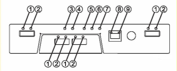
1
|
Link | Amber | At least one link has an error | All links have failed. |
|
2
|
Link Fault | Green | At least one link has an error. | Normal condition. |
|
3
|
Battery Fault | Amber | Indicates a fault within the battery backup unit. | Normal condition. |
|
4
|
Cache Active | Green | Caching is enabled. When blinking, the cache has data. |
Indicates a problem if caching is enabled. |
|
5
|
Service Action Allowed | Blue | The controller can be removed from the controller tray. | The controller cannot be removed from the controller tray. |
|
6
|
Service Action Required (Fault) | Amber | Indicates fault within the controller. | Normal condition. |
|
7
|
Power | Green | Power is present. | No power is applied to the controller tray. |
|
8
|
Ethernet Link | Green | The connection is active. | The connection is not active. |
|
9
|
Ethernet 100BASE-TX | Green | 100BASE-TX connection is active. | 100BASE-TX connection is not active. |
|
Location
|
LED Name | Color | On | Off |
|---|---|---|---|---|
|
1
|
IOM Link Fault | Amber | A link error occurred. | No errors have occurred. |
|
2
|
IOM Link | Green | The link is active. | A link error occurred. |
|
3
|
Service Action Allowed | Blue | The IOM can be removed from the expansion tray. | The IOM cannot be removed from the expansion tray. |
|
4
|
Service Action Required (Fault) | Amber | A fault exists within the IOM. | Normal Condition. |
|
5
|
Power | Green | Power is present in the drive expansion tray. | No power is applied to the drive expansion tray. |
|
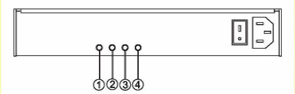
Location
|
LED Name
|
Color
|
On
|
Off
|
|---|---|---|---|---|
|
1
|
DC Power (DC Good) | Green | DC power from the power-fan assembly is available. | DC power from the power-fan assembly is not present. |
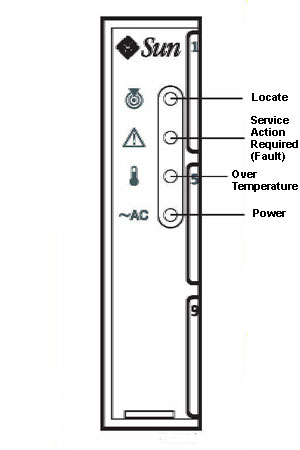
|
2
|
Service Action Allowed | Blue | The power-fan assembly can be removed from the tray. | The power-fan assembly cannot be removed from the tray. |
|
3
|
Fault | Amber | A fault exists within the power-fan assembly. | Normal condition. |
|
4
|
Power (AC Good) | Green | Power is present. | Power is not present. |
|
Copyright © 2011 Sun Microsystems, Inc. All rights reserved. Feedback | |||