| Home | Current Systems | Former STK Products | EOL Systems | Components | General Info | Search | Feedback |
|
|
Sun System Handbook - ISO 3.4 June 2011 Internal/Partner Edition | ||
|
|||
Sun Blade 150A41
|
||||||||||||||||||||||||||||||||||||||||||||||||||||||||||||||||||||||||||||||||||||||||||||||||||||||||||||||||||||||||||||||||||||||||||||||||||||||||||||||||||||||||||||||||||||||
|
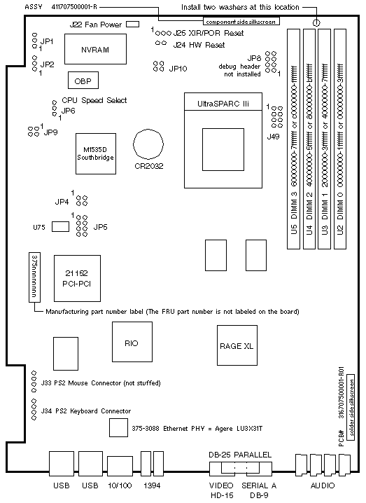
| JUMPER | PINS | SETTING | DESCRIPTION |
|---|---|---|---|
| JP3 | 1-2 3-4 5-6 |
In In In |
550MHz UltraSPARC IIi |
| JP3 | 1-2 3-4 5-6 |
Out Out Out |
650MHz UltraSPARC IIi |
| JP6 | 1-2 1-2 |
Out In |
Disable Registered DIMM (default) Enable Registered DIMM |
| Single Function PCI Cards | ||
|---|---|---|
| PCI Slot | MHz | Device Path |
| 3 | 33 MHz | /pci@1f,0/pci@5/<device>@0 |
| 2 | 33 MHz | /pci@1f,0/pci@5/<device>@1 |
| 1 | 33 MHz | /pci@1f,0/pci@5/<device>@2 |
| Multi Function PCI Cards | ||
|---|---|---|
| PCI Slot | MHz | Device Path |
| 3 | 33 MHz | /pci@1f,0/pci@5/pci@0/<device> |
| 2 | 33 MHz | /pci@1f,0/pci@5/pci@1/<device> |
| 1 | 33 MHz | /pci@1f,0/pci@5/pci@2/<device> |
| PART # | DESCRIPTION |
|---|---|
| F100-7192 100-7192 527-1023 527-1067 |
550MHz UltraSPARC IIi FRU w/ Ground Ring 550MHz UltraSPARC IIi KFAB650MHz UltraSPARC IIi KFAB
(deviation WO_25102)
550MHz/DB650MHz UltraSPARC IIi 550MHz UltraSPARC IIi KFAB650MHz UltraSPARC IIi KFAB
(deviation WO_25102)
550MHz/DB650MHz UltraSPARC IIi |
| F527-1079 100-7192 527-1078 527-1079 |
550MHz UltraSPARC IIi FRU w/ Ground Ring550MHz UltraSPARC IIi KFAB
(deviation WO_26984/WO_27317)
550MHz UltraSPARC IIi DMOS4550MHz UltraSPARC IIi DMOS4 |
| F527-1077 527-1023 527-1077 |
650MHz UltraSPARC IIi FRU w/ Ground Ring650MHz UltraSPARC IIi KFAB
(deviation WO_26984/WO_27317)
650MHz UltraSPARC IIi DMOS4 |
| F527-1023 527-1023 |
650MHz UltraSPARC IIi FRU w/ Ground Ring650MHz UltraSPARC IIi KFAB |
| Sun Blade 150 Refresh Codename: Grover+ Refresh |
| 375-3166 | 375-3167 | 375-3152 |
|---|---|---|
|
0MB Non-FRU 375-3152 + 550MHz ATO Option 6182A |
0MB Non-FRU 375-3152 + 650MHz ATO Option 6183A |
0MB FRU w/o UltraSPARC IIi September 2003 |
 |
|
* Components at J34, J49, JP5, and U75 were removed from 375-3152 by WO_29130 in April 2004. |
| JUMPER | PINS | SETTING | DESCRIPTION |
|---|---|---|---|
| JP1 | 1-2 2-3 |
In In |
Select Flash PROM (default) Select ROMBO |
| JP2 | 1-2 2-3 |
In In |
OBP write protected (default) OBP write enabled |
| JP4 | 1-2 3-4 |
In Out |
UltraSPARC IIi CPU (default) UltraSPARC IIi CPU (default) |
| JP5 | 1-8 | Out | UltraSPARC IIi CPU |
| JP6 | 1-2 2-3 |
In In |
550MHz UltraSPARC IIi CPU 650MHz UltraSPARC IIi CPU |
| JP9 | 1-4 | Out | OBP Configuration |
| J49 | 1-8 | Out | Debug header |
| Single Function PCI Cards | ||
|---|---|---|
| PCI Slot | MHz | Device Path |
| 3 | 33 MHz | /pci@1f,0/pci@5/<device>@0 |
| 2 | 33 MHz | /pci@1f,0/pci@5/<device>@1 |
| 1 | 33 MHz | /pci@1f,0/pci@5/<device>@2 |
| Multi Function PCI Cards | ||
|---|---|---|
| PCI Slot | MHz | Device Path |
| 3 | 33 MHz | /pci@1f,0/pci@5/pci@0/<device> |
| 2 | 33 MHz | /pci@1f,0/pci@5/pci@1/<device> |
| 1 | 33 MHz | /pci@1f,0/pci@5/pci@2/<device> |
| PART # | DESCRIPTION |
|---|---|
| F100-7192 100-7192 527-1023 527-1067 |
550MHz UltraSPARC IIi FRU w/ Ground Ring550MHz UltraSPARC IIi KFAB650MHz UltraSPARC IIi KFAB
(deviation WO_25102)
550MHz/DB650MHz UltraSPARC IIi |
| F527-1079 100-7192 527-1078 527-1079 |
550MHz UltraSPARC IIi FRU w/ Ground Ring550MHz UltraSPARC IIi KFAB
(deviation WO_26984/WO_27317)
550MHz UltraSPARC IIi DMOS4550MHz UltraSPARC IIi DMOS4 |
| F527-1077 527-1023 527-1077 |
650MHz UltraSPARC IIi FRU w/ Ground Ring650MHz UltraSPARC IIi KFAB
(deviation WO_26984/WO_27317)
650MHz UltraSPARC IIi DMOS4 |
| F527-1023 527-1023 |
650MHz UltraSPARC IIi FRU w/ Ground Ring650MHz UltraSPARC IIi KFAB |
|
Copyright � 2011 Sun Microsystems, Inc. All rights reserved. Feedback | |||