Enterprise 250
A26

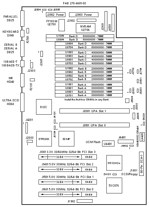
Jumper Settings
| JUMPER |
PINS |
SETTING |
DESCRIPTION |
| J0103 |
1-2
2-3 |
In
In |
Include CPU0 in scan chain
Bypass CPU0 in scan chain (default) |
| J0104 |
1-2
2-3 |
In
In |
UPA_REQ_SPARE High
UPA_REQ_SPARE Low (default) |
| J2604 |
1-2
2-3 |
In
In |
RS-232
RS-423 (default) |
| J2605 |
1-2
2-3 |
In
In |
RS-232
RS-423 (default) |
| J2702 |
1-2
2-3 |
In
In |
Select Flash PROM (default)
Select ROMBO |
| J2704 |
1-2
2-3 |
In
In |
FPROM write protect
FPROM write enable (default) |
| J2804 |
1-2
2-3 |
In
In |
FPROM flash recovery mode
FPROM normal mode (default) |
| J3001 |
1-2
2-3 |
In
In |
÷3 mode (250MHz/300MHz)
÷2 mode (200MHz) ÷4 mode (400MHz) |
| J3303 |
1-2
2-3 |
In
In |
Include CPU1 in scan chain
Bypass CPU1 in scan chain (default) |
| J4101 |
1-2
2-3 |
In
In |
Include UCM in scan chain
Bypass UCM in scan chain (default) |
| J4402 |
1-2
2-3 |
In
In |
Select RSC Flash PROM (default)
Select ROMBO |
| S4101 |
1-2 |
Out |
Unknown function of MPC823 (default) |
| S4301 |
1-2 |
Out |
RSC PBRST (default) |
PCI Slot Numbering
| SLOT |
BUS |
DEVICE TREE |
| 3 |
A |
pci@1f,2000/*@1,* |
| 2 |
B |
pci@1f,4000/*@2,* |
| 1 |
B |
pci@1f,4000/*@4,* |
| 0 |
B |
pci@1f,4000/*@5,* |
PCI Bus B shares the address/data bus with onboard Audio, Ethernet, Flash,
Floppy, Keyboard, Mouse, NVRAM, Parallel, SCSI, and Serial devices.
Enterprise 250
A26

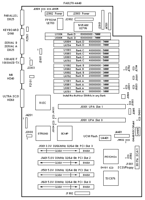
Jumper Settings
| JUMPER |
PINS |
SETTING |
DESCRIPTION |
| J0103 |
1-2
2-3 |
In
In |
Include CPU0 in scan chain
Bypass CPU0 in scan chain (default) |
| J0104 |
1-2
2-3 |
In
In |
UPA_REQ_SPARE High
UPA_REQ_SPARE Low (default) |
| J2604 |
1-2
2-3 |
In
In |
RS-232
RS-423 (default) |
| J2605 |
1-2
2-3 |
iIn
In |
RS-232
RS-423 (default) |
| J2702 |
1-2
2-3 |
In
In |
Select Flash PROM (default)
Select ROMBO |
| J2704 |
1-2
2-3 |
In
In |
FPROM write protect
FPROM write enable (default) |
| J2804 |
1-2
2-3 |
In
In |
FPROM flash recovery mode
FPROM normal mode (default) |
| J3001 |
1-2
2-3 |
In
In |
÷3 mode (250MHz/300MHz)
÷2 (200MHz) ÷4 (400MHz) ÷5 (tbd) |
| J3002 * |
1-2
2-3 |
In
In |
÷5 mode
÷2 mode, ÷3 mode, ÷4 mode (default) |
| J3303 |
1-2
2-3 |
In
In |
Include CPU1 in scan chain
Bypass CPU1 in scan chain (default) |
| J4101 |
1-2
2-3 |
In
In |
Include UCM in scan chain
Bypass UCM in scan chain (default) |
| J4402 |
1-2
2-3 |
In
In |
Select RSC Flash PROM (default)
Select ROMBO |
| S4101 |
1-2 |
Out |
Unknown function of MPC823 (default) |
| S4301 |
1-2 |
Out |
RSC PBRST (default) |
* J3002 was added in June 1999 to support 480MHz modules.
The Enterprise 250 480MHz module project was cancelled.
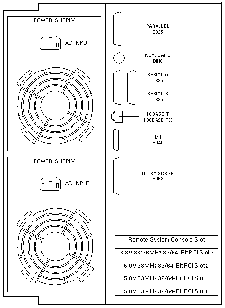
PCI Slot Numbering
| SLOT |
BUS |
DEVICE TREE |
| 3 |
A |
pci@1f,2000/*@1,* |
| 2 |
B |
pci@1f,4000/*@2,* |
| 1 |
B |
pci@1f,4000/*@4,* |
| 0 |
B |
pci@1f,4000/*@5,* |
PCI Bus B shares the address/data bus with onboard Audio, Ethernet, Flash,
Floppy, Keyboard, Mouse, NVRAM, Parallel, SCSI, and Serial devices.
Miscellaneous Connectors
| CONNECTOR |
PINS |
DESCRIPTION |
| J1902 |
1-50 |
Not used |
| J2303 |
1-8 |
Ethernet test (factory use) |
| J2601 |
1-8 |
Serial test (factory use) |
| J2801 |
1-3 |
Button XIR (1-2) and POR (2-3) |
| J2803 |
1-8 |
JSCC (factory use) |
| J2901 |
1-16 |
Sense Cable to Power Distribution Board |
| J2902 |
1-4 |
DC Power to Power Distribution Board |
| J2903 |
1-6 |
DC Power to Power Distribution Board |
| J2905 |
1-5 |
LED and Speaker (not used) |
| J3504 |
1-4 |
On/Off Switch (not used) |
| J4201 |
1-20 |
UCM Flex Cable |
| J4401 |
1-60 |
Not used |
| J4501 |
1-14 |
Sense Cable to Power Distribution Board |
|
Enterprise 250 Codename: Javelin |
Notes
- The minimum operating system is 2.5.1 HW: 11/97 or 2.6 HW: 5/98.
- Solaris 2.5.1 HW: 11/97 requires Enterprise 250 extensions.
- The flash PROM is soldered to the system board.
- Use the Flash PROM Programming Utility to update the flash PROM.
- Disconnect all system board power cables before removing or installing
the NVRAM. Failure to remove power can result in NVRAM corruption.
- Synchronous communication BugID 4162312 is fixed on 501-4681-06.
SCSI Bus Notes
- The internal SCSI bus is controlled by /pci@1f,4000/scsi@3.
- The external SCSI bus is controlled by /pci@1f,4000/scsi@3,1.
- RMA Tray SCSI cable <=530-2445-02 does not terminate the bus.
- Enable termination on the last device with SCSI cable <=530-2445-02.
Memory Notes
- The minimum requirement is four DIMMs in any bank.
- The recommended installation sequence is Bank A, B, C, D.
- Each bank addresses 512MB of memory.
Reference
 Enterprise 250 Owners Guide, 805-5160.
- Enterprise 250 ShowMe How, 724-2794.
 Flash PROM Programming Guide, 802-3233.
Rear View

|

